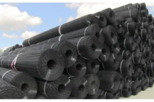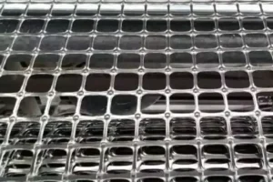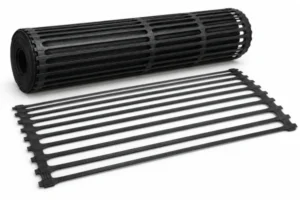
Choose the Load Path Before the Product Name
The decision between biaxial and uniaxial geogrid starts with the mechanism the design needs. Aggregate interaction beneath a trafficked surface and tensile reinforcement within a soil structure are not the same duty, even when both products are sold as geogrid.
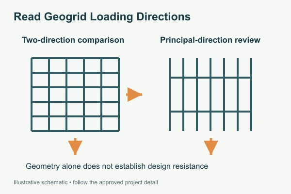
For biaxial vs uniaxial geogrid, identify the load direction, soil or aggregate interface, permitted deformation and required design evidence. The words “biaxial” and “uniaxial” describe directional characteristics; they do not prove that a particular product is suitable for every road or retaining structure.
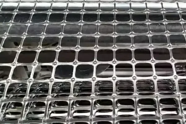
A square-looking aperture should not be treated as proof of equivalent directional performance. Likewise, a product with a strong principal direction still needs the correct orientation and connection arrangement in the installed work.
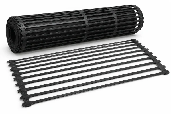
Review the geogrid product family with the actual section and specification, rather than selecting the highest printed tensile grade before understanding its function.
Compare Properties at the Strain and Direction That Matter
ASTM D6637 addresses geogrid tensile properties, while ASTM D7737 addresses individual junction strength. A junction result and a tensile result provide different information. Neither should be used as a substitute for the other. [3][4]
The biaxial source sheet lists BGSG20-20 strength at 2% elongation of at least 8 kN/m longitudinally and at least 10 kN/m transversely. The uniaxial sheet lists the HDPE BGUG50 grade with at least 50 kN/m tensile strength and at least 10 kN/m at 2% elongation in its stated principal series. Confirm the relevant test reports and direction for the proposed supply. [1][2]
These figures illustrate distinct products and property levels; they do not demonstrate equivalent structural performance. Avoid ranking the biaxial low-strain values directly against the uniaxial ultimate value.
| Design question | Biaxial candidate review | Uniaxial candidate review |
|---|---|---|
| Direction of required action | Both reported directions and aggregate interaction | Principal reinforcement direction and layout |
| Relevant deformation | Appropriate force–strain evidence | Appropriate force–strain and long-term evidence |
| Soil or aggregate interface | Grading, shape and installation arrangement | Interaction and anchorage required by the design |
| Connections | Panel continuity and relevant junction evidence | Connections or facing interface where specified |
The terminology alone does not determine design resistance. Use the product-specific evidence and the project’s calculation method for the actual application.
Make Orientation and Connections Visible on Site
Place direction arrows and product identification on the installation drawings where they affect performance. A roll should not be rotated merely because doing so reduces cutting if that rotation changes the required reinforcement direction.
Inspect the prepared foundation and keep the grid in the intended plane. Wrinkles, folded edges and displaced panels can disrupt the arrangement assumed by the designer. Use the accepted fixing or tensioning procedure without introducing damage.
Review joins and connections against the specific duty. A road-base overlap detail is not automatically an acceptable structural connection for a reinforced wall. Where facing connections are involved, the matching components and required evidence need to be identified before installation.
Observe aggregate placement and the first construction traffic sequence. Confirm that material passes through and around the apertures as intended, without the grid being pulled, torn or trapped in an unintended fold. Follow the approved cover and equipment restrictions.
Keep delivered roll labels associated with installed locations. Similar-looking products can differ in polymer, strength response, aperture geometry and coating. An unrecorded product change makes later conformity checks difficult, especially when the grid is already buried.
Check a Proposed Orientation Change
Consider a panel layout revised to reduce offcuts near a boundary. Confirm that the change preserves the required reinforcement direction, installed extent and connection arrangement. A lower waste quantity is useful only if the revised layout still satisfies the accepted design.
For a reinforced structure, show the relationship between the grid direction and the facing or connection detail. For an aggregate layer, show the arrangement assessed for that system. Do not carry an overlap or connection rule from one application into the other without review.
Keep the approved revision with the delivery and installation records. Mark any change in required product or roll format so purchasing and site supervision work from the same schedule. A drawing labelled simply “geogrid” can leave too much interpretation when biaxial and uniaxial products are both present on site. Product identification and direction should remain explicit until the layer has been accepted and covered.
Assess Long-Term Requirements Without Borrowing a Rating
For sustained tensile reinforcement, the long-term design strength can require product-specific consideration of creep, installation damage and durability. An ultimate tensile number should not be copied directly into a design-resistance field.
GRI-GG4 describes a framework for determining long-term geogrid design strength. The relevant factors must come from the selected product and applicable conditions, not a convenient value taken from another polymer or manufacturing construction. [5]
For an aggregate stabilisation application, assess the complete section using the design approach and performance evidence specified for that work. Replacing an accepted grid with another product solely because its ultimate strength is higher leaves the system comparison incomplete.
Commercially, compare the accepted design, installation and documentation package. Roll dimensions, connections, handling, waste and inspection requirements can affect installed cost. A lower material price may be offset by a more difficult layout or additional proof needed for acceptance.
Where a separate filtration or separation layer is required, include the appropriate geotextile rather than assuming the open grid performs that function.
Ask for an Application-Specific Proposal
A useful RFQ explains the design problem and identifies the evidence required for approval. “Biaxial or uniaxial, strongest available” does not provide a comparable procurement basis.
Include:
- Application, geometry and expected loading.
- Required directions and deformation criteria.
- Soil or aggregate information relevant to the interface.
- Product-specific tensile and junction requirements.
- Long-term design evidence where applicable.
- Connection, anchorage and facing details where required.
- Roll dimensions, installation constraints and quantity.
- Lot identification and conformity documentation.
When an alternative is proposed, request a comparison against the accepted design basis. Separate confirmed equivalence from information that still requires review. A similar appearance, a shared polymer or a matching ultimate grade is not enough on its own.
Provide the section and design requirements through our project inquiry page so the discussion starts with the intended load path.
References
Tech Note: Mark the required reinforcement direction on the drawing before optimising the roll layout or approving a product substitution.