A Wider Roll Can Still Produce a Poor Layout
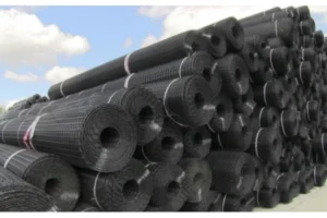
Geogrid roll size affects joints, cutting, handling and delivery. It also affects how easily the installer can preserve the direction and extent required by the design. Reducing waste by rotating a directional grid can create a technical problem that outweighs the quantity saving.
Begin with the approved reinforcement layout. Identify the required direction, layer position, panel extent and joining or connection detail. Then assess which available roll dimensions support that arrangement.
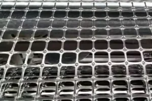
The geogrid product family includes different constructions and strengths. Do not assume all grades share one standard width, length, mass or packing arrangement. Confirm the actual supply dimensions for the selected product.
For a road-base application, the quantity plan may emphasise continuous coverage and placement sequence. For a reinforced structure, layer geometry and direction can be more restrictive. The same gross-area calculation cannot replace either drawing review.
Separate Product Performance from Roll Geometry
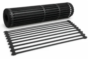
The uniaxial technical sheet lists HDPE BGUG50 with at least 50 kN/m tensile strength and at least 10 kN/m at 2% elongation. Its roll width and length are not stated in the audited table. Request a confirmed roll schedule rather than inferring dimensions from the strength grade. [1]
ASTM D6637 addresses tensile properties, not a universal commercial roll size. A strength designation should not be treated as evidence of width, length or shipping weight. [2]
| RFQ item | Information to confirm | Why it matters |
|---|---|---|
| Width and length | Actual offered dimensions and tolerances | Quantity and joint layout |
| Principal direction | Marking and relationship to roll direction | Correct installation orientation |
| Roll or bundle weight | Actual handling and packing information | Unloading and lifting plan |
| Joining detail | Approved overlap or connection | Continuity required by the design |
For a purely illustrative layout, a 4 m × 50 m roll has 200 m² gross area. If two 4 m widths overlap by an assumed 0.50 m, their combined coverage is 7.50 m, not 8 m. The overlap is an example for arithmetic only; the project detail determines the required arrangement.
Keep gross purchased area, net covered area and cut waste separate. Where a structural connection is required, do not model it as an arbitrary overlap merely to complete a quantity calculation.
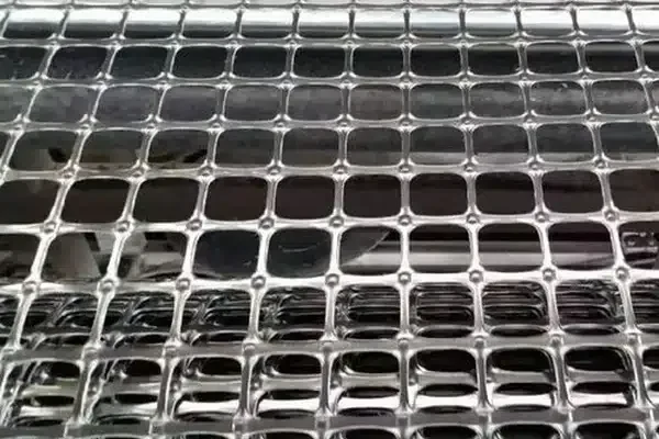
Organise Unloading and the Installation Sequence
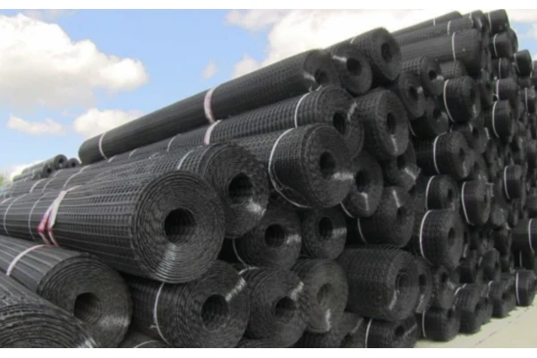
Check site access and unloading equipment before accepting the largest available roll. Confirm the actual package dimensions and weights, including any restrictions on lifting or storage. Handling information should come from the offered supply, not an assumed relationship between strength and weight.
Store rolls so labels remain readable and the material is protected from avoidable damage. ASTM D4873 provides guidance concerning identification, storage and handling of geosynthetic rolls and samples. Apply the relevant project and supplier instructions to the actual product. [3]
Mark installation direction on the drawing and confirm it at the first roll. The way a roll unrolls should be checked against the product information; it should not be assumed to establish the design direction in every construction.
Prepare the foundation and lay the grid without folds or unreviewed gaps. Use the approved fixing and joining details. Plan the fill-placement front so it does not drag the grid out of position or pull adjoining panels apart.
Keep part rolls identifiable. A clean offcut may be usable in an approved location, but its grade and direction still need to be known. Do not combine unlabelled remnants from different products merely to reduce waste.
Record roll usage by layer and zone. This connects procurement quantities to installation evidence and helps resolve shortages without guessing how much material remains in a partly used roll.
Keep Part Rolls Traceable
Consider a partly used roll reserved for a later reinforcement layer. Record its grade, direction, remaining usable dimensions and condition while the original identification is still available. A guessed remaining area is a poor basis for releasing the next installation quantity.
Check whether the later location permits the same joins or connections. An offcut that fits geometrically may still be unsuitable if it interrupts the required reinforcement extent or lacks a valid connection arrangement.
Include accepted part-roll usage in the revised layout and subtract it from the new procurement quantity only after approval. Otherwise, purchasing may reduce the delivery while the installer cannot use the assumed reserve. Keeping a simple part-roll register can prevent that mismatch without adding unnecessary complexity to the site paperwork. The register should connect physical material, approved location and the quantity schedule used for the next work stage.
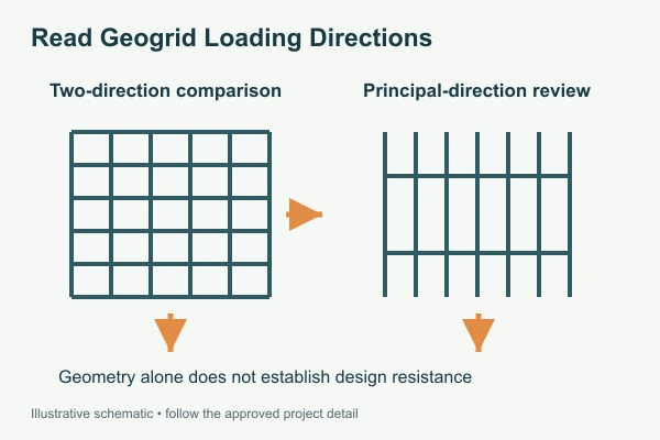
Compare Delivered Coverage and Labour Together
Wider or longer rolls can reduce some joins, but they can also complicate unloading, positioning and work in restricted spaces. Evaluate the layout and labour implications with the site team before choosing a commercial format.
Use a quantity schedule that separates the net design area, joins, cuts, reserve and whole-roll rounding. Avoid adding a general waste percentage on top of a detailed take-off that already includes the same losses.
For example, an assumed net requirement of 2,000 m² with a separately justified 6% cutting and reserve allowance gives 2,120 m² before rounding. If the hypothetical roll area is 200 m², eleven rolls provide 2,200 m² gross. Actual dimensions and the approved layout can change this result.
The comparison should include delivery phases and storage limitations. Material arriving too early can create congestion and exposure; material arriving too late can interrupt fill placement and inspection.
Do not let a convenient roll format override the accepted technical properties. A substitution that changes construction, polymer or tensile response requires its own review, even when the gross dimensions match perfectly.
Where a separate geotextile is specified, prepare its layout independently. Different roll widths can produce different joint positions and allowances within the same project footprint.
Release a Roll Schedule That Matches the Drawings
Before ordering, reconcile the supplier’s offer with the installation plan. Check both the material specification and the commercial dimensions so the site receives a usable package.
The schedule should identify:
- Accepted product, grade and conformity evidence.
- Required direction and installed-layer layout.
- Confirmed width, length and tolerances.
- Approved overlaps or structural connections.
- Cut strips, part rolls and reserve quantities.
- Package dimensions and handling weight.
- Delivery phases and storage arrangements.
- Roll labels and installed-zone traceability.
Ask for written confirmation where dimensions are absent from the technical sheet. A verbal assurance that the material is a “standard roll” leaves both quantity and handling unresolved.
Send the drawing and preferred supply format through our project inquiry page so the proposed roll schedule can be checked against the actual reinforcement layout.
References
Tech Note: Preserve the required reinforcement direction when optimising roll coverage; a reduction in waste does not justify rotating a directional product.